Medical City · Device Lab 2 of 69
MRI
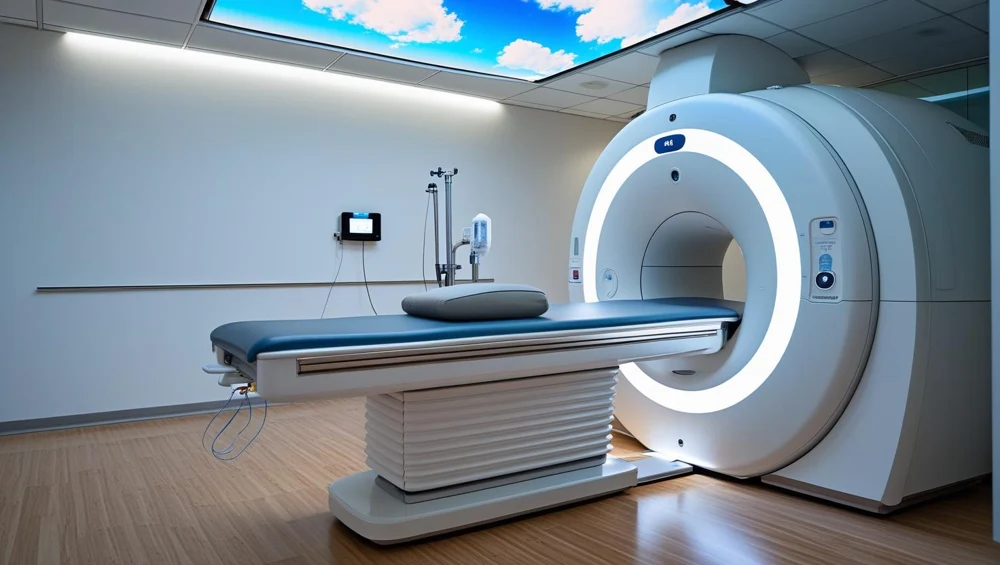
A horizontal-bore superconducting scanner. A persistent main field, three gradient axes and radiofrequency coils work together to acquire signals. The console controls a sequence; it does not photograph the patient directly.
- 10 parts
- 3 configurations in the Device Lab
- Also called: Magnetic Resonance Imaging, Mr Scanner, Mri Scanner
Configurations
The versions in the Device Lab.
1.5 T superconducting MRI
A horizontal-bore superconducting scanner. A persistent main field, three gradient axes and radiofrequency coils work together to acquire signals. The console controls a sequence; it does not photograph the patient directly.
3 T superconducting MRI
A higher-field horizontal-bore scanner with a superconducting magnet, gradient insert and radiofrequency chain tuned for its field. More available signal can support a different resolution or time trade-off; it is not a universal promise of a better examination.
Open permanent-magnet MRI
3 T permanent-magnet system with two opposing pole faces and a vertical main field. The patient lies in an open gap. Planar gradients and a compatible radiofrequency coil still encode and receive the signal.
How it works
Explore it in the Device Lab.
From alignment to excitation
Begin with the steady field. The net magnetisation has a longitudinal component. A controlled radiofrequency pulse changes its direction; the transverse component can contribute to a received signal.
Give the signal a spatial address
A received waveform mixes contributions from many places. Gradient fields let the system distinguish position through controlled frequency and phase changes. Slice selection also involves an appropriately designed radiofrequency pulse.
Make contrast a deliberate choice
The same phantom can look different under different sequence weightings. Tissue-related relaxation, timing and readout choices affect signal. Select each weighting and compare regions rather than judging the whole image as simply better or worse.
Separate motion from RF interference
A technical image problem has a pattern and a context. Motion can create displacement or ghosts; unwanted radiofrequency energy can create structured interference. Turn on one teaching disturbance at a time and compare with baseline.
The parts
Part by part.
Main magnet
The magnet establishes the steady field around which the rest of MRI is organised. It changes the balance and behaviour of nuclear magnetisation; it does not emit the image.
Shim system
Shimming improves how uniform the main field is over the region being examined. If different places experience unintended frequency differences, signal and geometry can suffer.
Gradient coil assembly
Gradients deliberately make resonance depend on position. That gives a received signal a spatial address.
Radiofrequency transmit structure
A brief radiofrequency field tips the net magnetisation away from equilibrium. That prepares a measurable transverse signal.
Local receive coil
The coil close to the anatomy detects a small changing electromagnetic signal. Placement matters: a technically impressive scanner still needs a suitable receiving path near the region of interest.
Coil connection interface
This is the boundary between a removable patient-side coil and the scanner receiving system. Correct mechanical engagement does not automatically prove the electrical channels are intact.
Patient table and drive
The table positions the anatomy in the intended imaging region. Its indicated coordinate is useful only when the patient, coil and landmark agree with it.
Positioning controls and landmark
A landmark connects the physical patient position to the planned scan volume. The operator uses the prescribed positioning method rather than guessing from the shell opening.
Hearing protection
Gradient switching makes the acoustic environment part of preparation. Protection must fit and be suitable for the examination; placing an accessory near the patient is not the same as providing effective protection.
Patient call system
The patient needs a reliable way to report discomfort or request attention. The call device closes a human feedback loop that image acquisition alone cannot provide.
Training cases
Guided training cases.
The missing receive channel
The coil is not fully recognised. What happens next?
The image that will not hold still
The patient reports discomfort during acquisition. What is the next priority?
The stripe that survives a repeat
The pattern persists with a stationary phantom. Which comparison is useful?
Acquisition stops, the magnet remains
The stop has interrupted scanning. Which statement is safe?
Training cases written by BMEssentia for teaching.
Simulations
Where it appears in the simulations.
Model notes