Medical City · Device Lab 11 of 69
Anaesthesia Machine
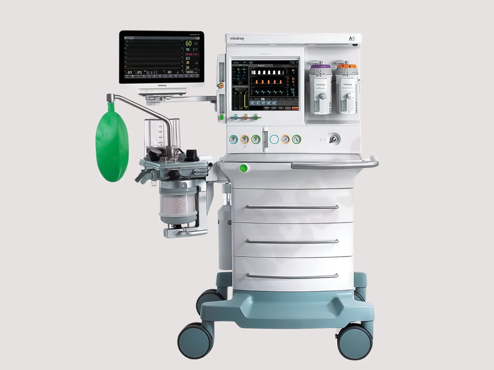
Flow is set through sensors and valves and shown on a screen. The hypoxic guard is a limit inside a controller, the ventilator is part of the same machine, and almost nothing about the gas path is visible from the front.
- 10 parts
- 2 configurations in the Device Lab
- Also called: Anesthesia Machine, Anaesthetic Machine, Anesthesia Workstation
Configurations
The versions in the Device Lab.
Electronic anaesthesia workstation
Flow is set through sensors and valves and shown on a screen. The hypoxic guard is a limit inside a controller, the ventilator is part of the same machine, and almost nothing about the gas path is visible from the front.
Pneumatic anaesthesia machine
Flow is set through needle valves and read from floats in glass tubes. The hypoxic guard is a chain and a gear between the oxygen and nitrous controls, and an oxygen failure device shuts the nitrous off and sounds a whistle with no power at all.
The parts
Part by part.
Pipeline inlets and cylinder yokes
Two ways in for every gas, at the back of the machine. A hose to a pipeline that comes from somewhere else in the building, and a yoke for a cylinder that hangs on the machine itself.
Regulators and pressure gauges
A row of round faces below the controls, and behind them the parts that turn a cylinder at a pressure that would destroy the machine into a supply it can use. The gauges are the only place on the machine that tells you anything about the world upstream of it.
Vaporisers and manifold
One or two upright blocks on a shelf at the top right of the machine, each holding a litre or so of a volatile liquid. Turn a dial and the machine adds a measured concentration of that agent’s vapour to the gas leaving it.
Oxygen flush
A single recessed button, usually green, that delivers oxygen straight to the common gas outlet at a flow nothing else on the machine can produce. It bypasses the flowmeters and it bypasses the vaporisers entirely.
Common gas outlet
One fitting, usually behind or beside the breathing system, where everything the machine has done arrives. Every gas, every flow setting and every turn of a vaporiser dial ends up here as a single stream, and from here it is the breathing system’s problem.
Absorber head and ports
A machined metal block on the left of the machine with everything screwed into it: the two ports the patient’s hoses leave from, the bag, the valve that sets pressure, and the canister hanging underneath. It is the junction where the circle becomes a circle.
Carbon dioxide absorbent canister
A clear jar of pale granules under the absorber head. It is a chemical reactor with no power, no controls and no output signal, and it is the only thing standing between a patient and the carbon dioxide they breathed out a minute ago.
Inspiratory and expiratory valves
Two ports on the front of the absorber head with a light disc sitting on a seat under a transparent dome. They are the only things in the whole breathing system that make it a circle rather than a corridor, and they do it with no power and almost no moving mass.
Reservoir bag, arm and APL valve
A soft bag on a short arm, and a knurled knob beside it. The bag is the oldest monitor in the room and the knob is the only pressure control a hand-ventilating anaesthetist has.
Bellows and housing
A concertina of soft material inside a clear cylinder above the absorber. It is what stands between the ventilator’s drive gas and the gas the patient breathes, and it is the most informative thing to look at on the whole machine.
Simulations
Where it appears in the simulations.
Next