Medical City · Device Lab 27 of 69
Insulin Pump
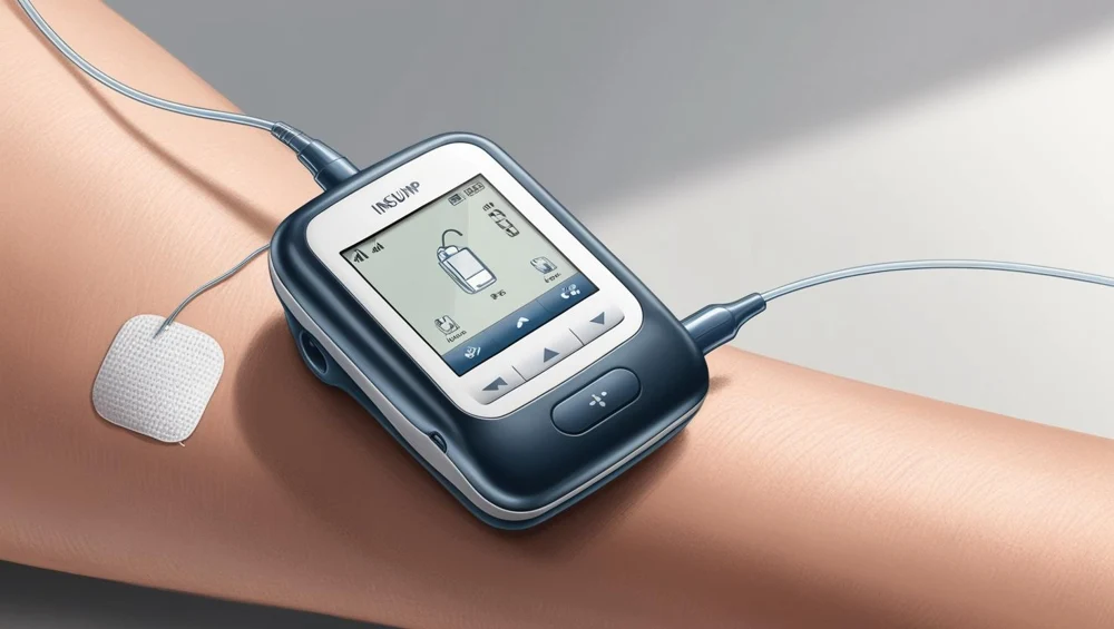
A moulded case the size of a pager, worn on a waistband, containing a cell, a controller, a gearbox-and-lead-screw drive and a 3 mL reservoir barrel whose plunger the screw advances. A window in the side shows the barrel and the plunger. 60 m long leaves the bottom of the case and ends at a cannula under a dressing.
- 10 parts
- 2 configurations in the Device Lab
Configurations
The versions in the Device Lab.
Tethered syringe-driver pump with a compliant infusion set
A moulded case the size of a pager, worn on a waistband, containing a cell, a controller, a gearbox-and-lead-screw drive and a 3 mL reservoir barrel whose plunger the screw advances. A window in the side shows the barrel and the plunger. 60 m long leaves the bottom of the case and ends at a cannula under a dressing.
On-body patch pump with a rigid metering chamber and no set
A smooth lozenge adhered directly to the skin, containing a 2 mL reservoir, a cell, a controller and a rigid metering chamber of 1 mm bore swept 50 micrometres at a time between two mechanically seated check valves. There is no set and nothing leaves the pod: 40 mm of soft silicone link inside the shell carries the fluid from the outlet valve to the cannula. Delivery is a count of completed strokes, and that count is also how occlusion is detected.
How it works
Explore it in the Device Lab.
The pressure hierarchy, and where the device lives in it
Set the bench to its nominal state and read the five pressures on the ladder. They are the whole device.
The alarm delay, and the identity that explains it
Block the outlet on the bench and read the delay. Then read the line time constant beside it. One is minutes and the other is milliseconds, and they are the same physics.
The increment, and why delivery is not smooth
Watch the manometer needle while the outlet is blocked. The pressure does not rise smoothly. It rises in treads, one every ten seconds, and the sixty-fourth tread crosses the threshold.
Storage against delivery, and the bolus that comes back
Run the rig against a blocked outlet until it alarms, and compare two readings. The counter says one point seven seven microlitres. The balance says nothing arrived.
One bubble, and the architecture it ruins
Set one microlitre of gas on each configuration in turn and read the multiplier. The tethered pump delay grows by a factor of one point three nine. The patch pump delay grows by seven point nine six.
The parts
Part by part.
Reservoir barrel and the fluid it holds
A transparent barrel holding three millilitres, nine and a half millimetres across the bore, visible through a window in the side of the case with a plunger part way down it. On the other configuration it is a collapsing pouch inside a sealed pod instead, holding two millilitres, and nothing about it can be seen at all.
The moving seal between the mechanism and the fluid
A ribbed elastomer plunger four millimetres thick running in the barrel, with two sealing ribs and a short steel rod at its back. On the other configuration a single O-ring on a piston one millimetre across.
Outlet port, septum and the connection to the line
A short moulded boss at the bottom of the case with a pierced rubber septum in it and, on the tethered configuration, a tapered fitting below that. It is three millimetres of plastic, and it is the last place in the whole system where anything about the fluid is known.
The compliance chain, which is the whole device and is not a part
Not a component at all. It is the total springiness of everything between the metering element and the outlet, drawn on the schematic stand as four sections at twenty-two times life size with a bar under each showing its share.
Trapped gas, and the compliance it multiplies
A bubble. One microlitre of it is one point two four millimetres across; ten microlitres is two point six seven.
Soft cannula, dressing and the schematic interface
A dressing on the outside of the clothing, a small moulded hub and, on the schematic stand and nowhere else, a section of the cannula itself at twenty-two times life size beside a labelled tissue section. No puncture is depicted anywhere in this model.
The actuator that turns electricity into displacement
A stepper motor five and a half millimetres in radius and fourteen long, with two leads, on the tethered configuration. On the patch, a shape-memory alloy wire a third of a millimetre thick, a lever on a pivot and a return spring.
Position feedback, and the only delivery figure the device has
An optical disc with twelve slots turning with the motor shaft, and a slotted optical switch reading it. On the patch configuration, a contact that closes when the piston reaches the end of its stroke.
Pressure sensing, its range and its one count
A force cell with two strain gauges on it, sitting behind the thrust bearing at the end of the lead screw, on the tethered configuration. On the patch, a tiny diaphragm and die over the outlet channel.
Controller, the rate scheduler and the increment clock
A green board forty millimetres by fifty-six carrying a microcontroller, a crystal, a regulator, a motor driver and a handful of passives. On the patch a smaller board doing the same job.
Simulations
Where it appears in the simulations.
Model notes
Real models, reviewed.
Next