Medical City · Device Lab 39 of 69
ECG
Ten electrodes: one on each limb and six across the chest, every one of them found from bony landmarks by whoever is recording. The four limb electrodes go at the wrists and ankles. Nine of the ten become node potentials and the tenth appears in no lead definition at all, so twelve traces are computed from eight independent measurements.
- 10 parts
- 2 configurations in the Device Lab
- Also called: Ekg, Electrocardiograph, 12-Lead
Configurations
The versions in the Device Lab.
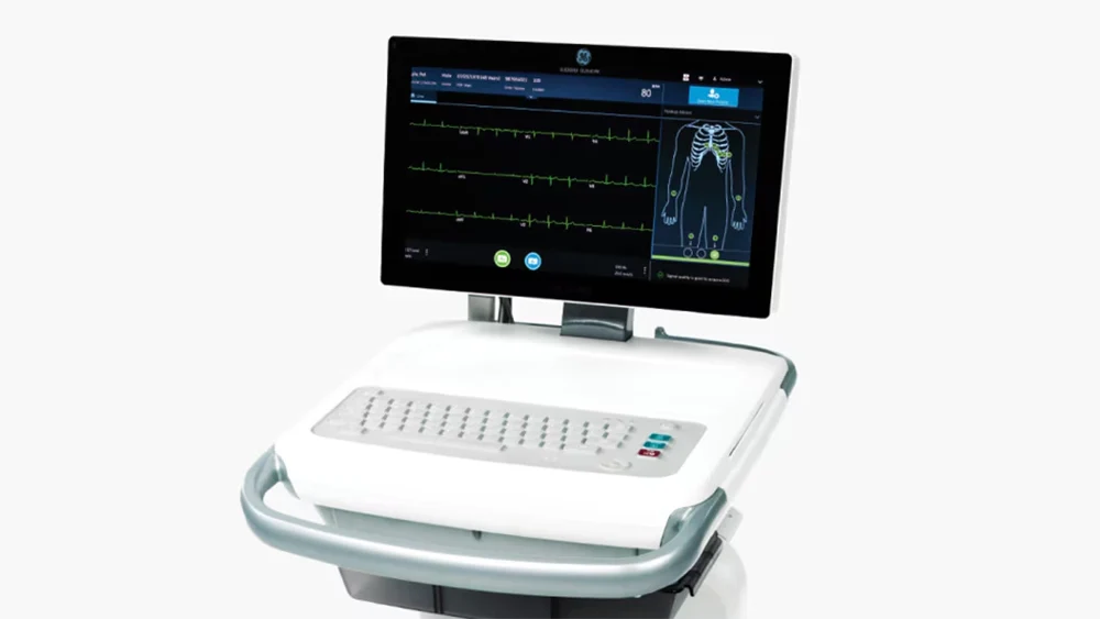
Twelve-lead diagnostic recorder, ten electrodes
Ten electrodes: one on each limb and six across the chest, every one of them found from bony landmarks by whoever is recording. The four limb electrodes go at the wrists and ankles. Nine of the ten become node potentials and the tenth appears in no lead definition at all, so twelve traces are computed from eight independent measurements.
Continuous five-electrode monitoring configuration
Five electrodes, all of them on the torso: the four limb electrodes moved off the limbs on to the trunk so that an arm can be moved without moving a trace, and one precordial electrode. Four of the five become node potentials and the fifth appears in no lead definition, so seven traces are computed from three independent measurements. The band runs from half a hertz to forty, sampled at two hundred and fifty, and the electrodes stay where they were put for hours or days.
How it works
Explore it in the Device Lab.
Move the lower corner, watch a feature appear
Hold the illustrative complex and everything else still, and change only the lower corner. Read the baseline displacement immediately after the deflection.
Integrate the output and find out why the feature had to exist
Change nothing but the length of the window you integrate over, and watch the total area under the filtered output.
Move the same corner again, and watch the wander instead
Leave the complex alone. Set a baseline drift of an illustrative one millivolt per second, which is a declared bench control rather than a measurement of anybody, and read the steady output at each corner.
Move the upper corner, watch amplitude leave
Hold the illustrative upstroke at twenty milliseconds and change only the upper corner. Read the height the apex reaches as a fraction of what went in.
Delete a channel and ask the rank what it cost
Turn off displayed traces one at a time, in any order, and read the rank of what is left.
The parts
Part by part.
Disposable pre-gelled electrode, its element and its contact
Ten small foam discs on a peel-off strip, each a few centimetres across, each with a metal stud moulded through its back and a bead of wet gel in a shallow well on its front. Tilt the strip and the gel moves.
Lead wires, the colour code and the yoke
Ten slim coloured wires, each ending in a clip or a stud socket, each printed with a position name, gathered at a moulded yoke where they all leave for the trunk cable. The colours are the only thing distinguishing one from another once they are on a body.
Patient trunk cable, its screen and its connector
One thick cable a couple of metres long, a moulded keyed connector at the instrument end and the lead wire yoke at the other, with a drape hook part way along. It is the heaviest flexible thing on the machine and the one most often replaced.
The right-leg electrode, which appears in no lead at all
One disc exactly like the other nine, low on the right side, with a wire in the odd colour out. On the front panel it has an indicator of its own next to the others, and on the twelve panes it has nothing.
Defibrillation protection and input current limiting
Immediately behind the patient connector, a row of ten identical little networks on the acquisition board, each a resistor and a clamping device, with nothing to adjust and no indicator. In ordinary use none of it does anything at all.
Acquisition module and the input multiplexer
A shielded box behind the patient connector with the ten protected inputs entering one face and a digital ribbon leaving the other. There is nothing to adjust on it and a legend on the lid giving the band and the sample rate for each configuration.
Wilson central terminal network, and the average nobody measured
Three identical resistors on the acquisition board, sitting side by side, with one end of each going to a limb input and the other ends joined at a single point. A single track leaves that point and goes to every one of the precordial difference stages.
Differential amplifier and the electrode offset it must survive
One instrumentation stage per lead on the acquisition board, a row of identical small packages with no adjustment brought out anywhere on the outside of the instrument. There is nothing on the front panel that changes the gain.
The low-frequency corner, and the displacement it manufactures
Nothing visible. A legend on the front panel giving the band, a key on some instruments that moves the lower figure, and a line in the record header naming what was used.
The high-frequency corner, and the amplitude it removes
Nothing visible again. A figure in the same panel legend, a hundred and fifty on one configuration and forty on the other, and the same figure in the record header.
Simulations