Medical City · Device Lab 18 of 69
Autoclave
Steam admitted at the top of the chamber and air allowed to fall out of a drain at the bottom. There is no pump, no sub-atmospheric step and nothing at all driving the air except the fact that it is denser than steam. The holding condition is a hundred and twenty-one degrees for fifteen minutes, and the extra twelve minutes over the pre-vacuum cycle are being spent on the same lethality at a lower temperature.
- 10 parts
- 2 configurations in the Device Lab
- Also called: Steam Steriliser, Steam Sterilizer
Configurations
The versions in the Device Lab.
Gravity displacement, solid and fluid loads
Steam admitted at the top of the chamber and air allowed to fall out of a drain at the bottom. There is no pump, no sub-atmospheric step and nothing at all driving the air except the fact that it is denser than steam. The holding condition is a hundred and twenty-one degrees for fifteen minutes, and the extra twelve minutes over the pre-vacuum cycle are being spent on the same lethality at a lower temperature.
Pulsed pre-vacuum, porous and hollow loads
A liquid-ring pump pulls the chamber down to about a tenth of an atmosphere, steam refills it to roughly two bar, and the sequence repeats. Only after that does the temperature phase begin, which is why the cycle chart on the wall of a sterile services department is mostly a sawtooth with a plateau on the end. The holding condition is a hundred and thirty-four degrees for three minutes.
How it works
Explore it in the Device Lab.
The pocket the gauge cannot see
Set a wrapped or hollow load and watch four numbers move together: the residual air fraction, the steam partial pressure, the pocket temperature, and the log reductions the pocket achieves.
An exponent, not a habit
Step the pulse count from one to six and watch the residual air fall. Then change the vacuum floor and watch what happens to the same curve.
The number that actually decides it
Set the pulse count to three and the leak rate to zero, note the residual air in millibars, then raise the leak rate through the permitted limit and past it.
Steam that will not condense
Raise the plant supply pressure with the supply dryness at one, and watch the superheat appear. Then lower the dryness a little and watch it vanish.
Why eight degrees is a factor of six
Hold the time constant and step the temperature, watching F0, the log reductions and the number of survivors from a population of a million.
The parts
Part by part.
Chamber vessel and pressure boundary
A rectangular stainless steel box with radiused corners, about six hundred and sixty millimetres each way and a little deeper, welded from five-millimetre plate, with an aperture at each end and a shallow sump in the floor. Three hundred litres.
Steam jacket and insulation
A second shell about twenty millimetres outboard of the chamber, forming a closed annular space around five of its six faces, filled with steam at its own pressure. Outside that, fifty millimetres of insulation blanket, and outside that the painted cladding panels a person actually touches.
Door, seal and interlock
A stainless slab with a stiffening rib, a viewing port on the clean side, rising vertically into a headbox above the aperture on a pneumatic ram and a chain. Around the aperture, a hollow silicone gasket in a groove.
Loading carriage, shelves and the load
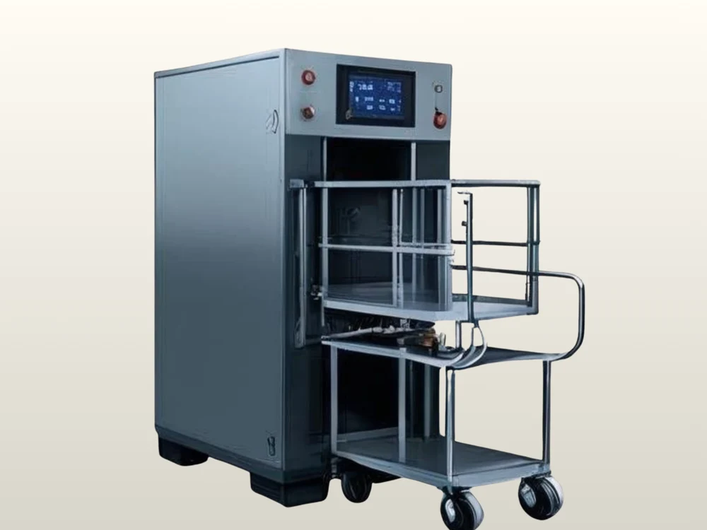
A stainless frame on four castors with a perforated or wire deck at nine hundred millimetres, a second shelf above it, and a push handle. On it: trays, wrapped packs, pouches.
Plant steam supply, isolation and separator
A lagged pipe dropping from the ceiling on the service side, with an isolating valve and its hand-wheel, a Y-pattern strainer, and a separator: a small vessel with a baffle in it and its own trap on the bottom. A pressure gauge reads what arrives before anything is done to it.
Pressure-reducing valve and the superheat it makes
A cast body with a large spring bonnet on top, an adjusting screw and a lock nut, a small pilot line running back from downstream, and a gauge on the outlet reading the pressure the chamber will see. It is a regulator rather than a restrictor: it holds a set outlet pressure regardless of what the inlet does.
Integral steam generator and feedwater
A short fat pressure vessel with domed ends under the chamber, about two hundred millimetres across and three hundred tall, with a bolted element flange low on one side, a sight glass and two level probes, a feedwater pump, a softener cartridge and a blowdown valve at the lowest point.
Chamber admission valve and baffle
A diaphragm valve body high on the machine with a pneumatic actuator on top of it and a small solenoid pilot beside that, feeding a pipe that enters the chamber through the jacket and the insulation at the top. Inside the chamber, the pipe ends at a spreader rather than at an open end.
Drain line and the reference measuring point
A pipe from the chamber sump running down through the service space to a tundish, an open funnel with an air gap above it, and then to the building drain. Part way down, a machined pocket carrying the reference temperature sensor.
Air detector
A small steel bulb with a cooling jacket round it, a narrow sensing line to the chamber, a comparator box beside it and a single lamp on the front of the machine. It is the only component whose entire purpose is to notice the thing the rest of the machine cannot see.
Simulations
Where it appears in the simulations.
Next