Medical City · Device Lab 31 of 69
Cranial Drill
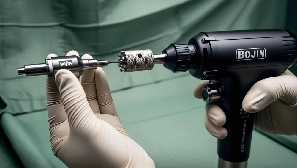
A two-part tool on a Hudson shank: an outer conical cutter about fourteen millimetres across that makes the hole, and an inner pilot drill of four millimetres that leads it by two. Between them is a clutch held together by nothing but the axial load coming back up the pilot. Drive it with a light hand and it will not cut at all, because the pilot's share of the thrust never reaches the spring preload.
- 10 parts
- 2 configurations in the Device Lab
- Also called: Cranial Perforator, Craniotome
Configurations
The versions in the Device Lab.
Self-arresting perforator, 14 mm cutter over a 4 mm pilot
A two-part tool on a Hudson shank: an outer conical cutter about fourteen millimetres across that makes the hole, and an inner pilot drill of four millimetres that leads it by two. Between them is a clutch held together by nothing but the axial load coming back up the pilot. Drive it with a light hand and it will not cut at all, because the pilot's share of the thrust never reaches the spring preload.
Craniotome, 2.3 mm bur over a dural footplate
A small fluted bur of a little over two millimetres running at tens of thousands of revolutions a minute, with a polished steel footplate fitted round its nose. The footplate is introduced through a hole the perforator has already made and slides in the epidural space with the bone above it and the dura below it. The bur flute is held a fixed one millimetre above the footplate's lower face, so what it cuts is the bone the footplate is riding under, and the tool is fed sideways along the line of the flap rather than pushed into the bone.
How it works
Explore it in the Device Lab.
The clutch sees a fixed fraction of your hand
Set a thrust and read what the comparator is actually being given, then find the thrust below which the tool will not cut at all.
The release is fast. That is not the problem
Derive the release and then compare it against the room it has. Two numbers, both closed form, and neither of them depends on how hard bone is to cut.
What it cannot tell from bone
Load the flutes and watch the comparator stay satisfied through a breakthrough. Then work out how little it takes.
What the speed tells you, and on which drive
Change the drive and watch what happens to the one piece of feedback the operator has.
A margin that cannot be spent, only bent
Change every control on the bench and watch the clearance not move.
The parts
Part by part.
Control console, irrigation pump and footswitch
A wheeled box at chest height with a small screen, six keys, two knobs and two round gauges on its front, a roller pump bolted to one side and a saline bag on a pole above it. A two-pedal footswitch lies on the floor with a cable running back up to it.
Drive motor and torque-speed curve
A sealed can about thirty millimetres across at the back of the handpiece, with a ring of exhaust slots and a muffler behind it. It is the only part of the set that does work, and everything in front of it exists to deliver what it makes to two millimetres of bone.
Handpiece body, bearings and nose
A knurled aluminium barrel about twenty-six millimetres across and a hundred and twenty long, tapering to a smaller nose at the front. It is the part a hand actually holds, and its diameter and knurl are the reason a hand can hold it steadily while pushing on it.
Hudson coupling and tool retention
A short socket in the nose of the handpiece with a knurled sleeve round it and three small balls set into its wall. Twist the sleeve, push a shank in, release it, and the tool is held.
Trigger, throttle and speed regulation
A lever under the barrel on a pivot pin, with a small collar beside it marked for a safe position and a run position. Pressing it starts the tool; it has travel in it, so it is a throttle rather than a switch.
Supply hose and its connectors
A braided hose about eleven millimetres across, a metre and a half of it, running from a fitting on the console to a collar nut on the back of the handpiece. It is the least regarded part of the set and it is in series with everything.
Irrigation nozzle, line and flow setting
A bag of saline on a pole, a drip chamber, a roller clamp, a length of tubing through the pump head, and then a line clipped along the barrel to a small nozzle beside the nose that is aimed at the cutting edge. The nozzle is the whole point: everything upstream of it exists to get fluid to that one place.
Motor cooling, exhaust and swarf clearance
A muffler behind the motor with ten exhaust slots round it, four rings of baffle, and at the other end of the barrel a clear shroud round the nose with a small suction stub coming off it. Two flows, going in opposite directions, doing two different jobs.
Hand rest, grip and depth reference
A soft pad on the underside of the barrel with five ribs across it, and forward of it a knurled collar with eight graduation marks round it. One is for the hand and one is a scale, and a plate beside them says the scale is a reference and not a stop.
Sterile tray, stand and bench feed fixture
A stainless tray on a five-legged wheeled stand at instrument height, draped, with the set laid out on it, and standing on the tray a small column with a carriage on it holding the handpiece nose down over a test block. Two of those three things belong in a theatre and one belongs on a bench.
Model notes
Real models, reviewed.
Next