Medical City · Device Lab 24 of 69
Pacemaker
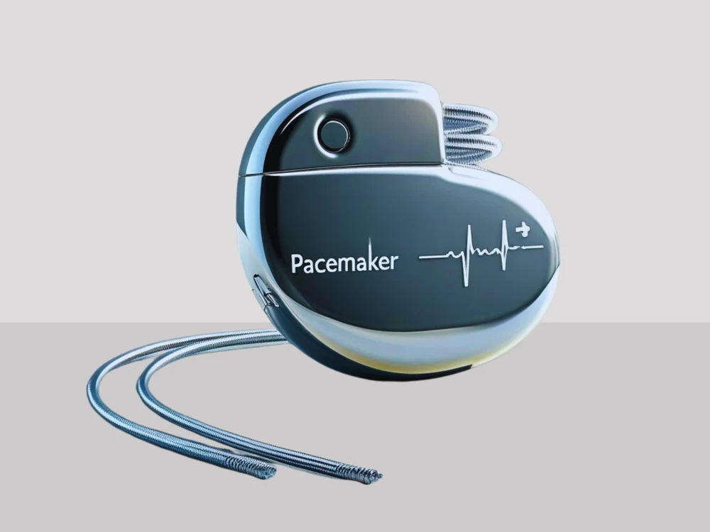
A sealed generator beneath the upper chest connects to one ventricular lead. It senses local ventricular electrical activity and supplies a small pacing pulse when its timing rules call for one.
- 10 parts
- 5 configurations in the Device Lab
Configurations
The versions in the Device Lab.
Single-chamber transvenous pacemaker
A sealed generator beneath the upper chest connects to one ventricular lead. It senses local ventricular electrical activity and supplies a small pacing pulse when its timing rules call for one.
Dual-chamber transvenous pacemaker
A generator connects to separate right atrial and right ventricular leads. Two sensing channels and coordinated timers allow the device to respond to activity in both chambers.
Cardiac resynchronisation pacemaker · CRT-P
A pacing-only resynchronisation system coordinates right and left ventricular stimulation. The illustrated arrangement also has an atrial lead. Its left ventricular lead follows a coronary vein on the outside of the left ventricle.
Leadless ventricular pacemaker
A miniature sealed pacemaker sits inside the right ventricle. Its battery, electronics and electrodes occupy one capsule. This representative ventricular configuration has neither a chest pocket nor a transvenous lead.
The parts
Part by part.
Hermetic generator enclosure
The implanted generator is the small metal unit under the skin. It encloses the energy source and electronics; it is not the electrode that normally sits against the heart.
Lead connector header
The header receives the proximal ends of the implanted leads. It is the transition from the generator to the lead system.
Hermetic feedthrough
Conductors must leave a sealed implanted enclosure while its interior remains protected from body fluids. The feedthrough is the engineered boundary that makes those two requirements compatible.
Battery and energy reserve
The battery supplies energy for sensing, timing, communication and pacing. A pacemaker spends much of its life listening and keeping time, not producing continuous large pulses.
Timing controller and memory
The controller decides when an eligible sensed event resets a timer and when a pacing pulse is due. It does not simply produce a fixed tick regardless of what the heart is doing.
Sensing amplifier and input protection
The sensing channel listens for the small electrical signal available at the pacing electrodes. It conditions that signal and decides whether an event meets its detection rules.
Implant communication interface
The implant communication interface exchanges data with the external programmer. It lets the clinical team inspect settings and stored evidence without physically opening the generator.
Activity sensor and rate-response input
Some pacing systems use sensor information to adapt pacing behaviour when intrinsic rate response is inadequate. In this representative transvenous model, an activity sensor reports movement to the controller.
Pulse output stage
The output stage turns a timing command into a controlled electrical pulse. Pulse amplitude and pulse width describe different properties: how large the pulse is and how long it lasts.
Programmer and recorded evidence
The programmer is the clinician-facing interface used to communicate with the implanted system. It can present settings, stored information, electrograms and event markers.
Next