Medical City · Device Lab 25 of 69
VNS
0 C derived from the drawn block rather than typed in. There is no second interface: the only way energy gets into this device is at the factory, and the only way the empty one leaves is in an operating theatre.
- 10 parts
- 2 configurations in the Device Lab
- Also called: Vagus Nerve Stimulator, Vagal Nerve Stimulator
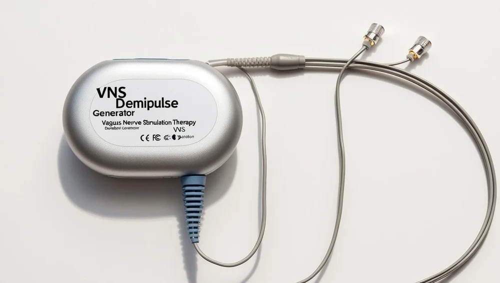
Configurations
The versions in the Device Lab.
Primary-cell pulse generator, replaced at depletion
0 C derived from the drawn block rather than typed in. There is no second interface: the only way energy gets into this device is at the factory, and the only way the empty one leaves is in an operating theatre.
Rechargeable pulse generator, energy coupled through the skin
7 V, behind a resonant receive coil, a rectifier and a temperature sensor that throttles the charge. It buys a renewable budget and pays for it with a whole second interface through the skin, with its own coupling, alignment and heating arithmetic.
The parts
Part by part.
Hermetic titanium enclosure and weld seam
A flat titanium box, 52 mm by 46 mm and 8 mm thick, with corners you could hold in a closed hand. It is welded shut.
Ceramic-to-metal hermetic feedthrough
A small ceramic disc at one end of the can with four platinum pins passing straight through it. It is the only place in the whole sealed volume where anything crosses from inside to outside, and it is about seven millimetres across.
Moulded connector header
The moulded block sitting on the top edge of the can, about 13 mm deep and 10 mm tall, made of a translucent amber epoxy so that everything inside it can be seen. It is where the lead plugs in.
Lead bore, setscrew block and sealing septum
A small metal block inside the header with a bore through it for the lead and a threaded hole at right angles for a setscrew. Above the setscrew sits a silicone septum that reseals itself after the driver is withdrawn.
Low-power controller, timing reference and program store
A single low-power integrated circuit on the hybrid board, about seven millimetres square, with the timing reference beside it. It decides when a pulse happens and how wide it is, and it holds the stored parameters between one telemetry session and the next.
Switched-capacitor voltage multiplier
A switched-capacitor voltage multiplier: a handful of capacitors and switches occupying about five millimetres by four on the board. It takes the cell rail and makes a higher one, in whole multiples and nothing in between.
Programmable constant-current output stage
The programmable constant-current source: about six millimetres by five, sitting next to the multiplier. It is what actually makes the pulse, and what makes it is a current rather than a voltage.
Series direct-current blocking capacitor
7 microfarads, five millimetres by three by two, wired in series between the output stage and the feedthrough. It is the largest passive component on the board and it is there to guarantee one thing: that no direct current reaches the tissue.
Output multiplexer and passive recharge switch
A small multiplexer and shorting switch, four millimetres square, standing between the output stage and the feedthrough pins. It decides which contact is the cathode, and it also shorts the two together between pulses.
Cuff impedance measurement circuit
A small measurement circuit, about five and a half millimetres by four, that puts a known sub-threshold current down the lead and reads the voltage it develops. It is the only instrument this implant has pointed at its own output, and it produces one number.
Model notes