Medical City · Device Lab 58 of 69
Nebulizer
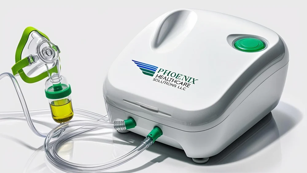
A bench compressor drives air through small-bore tubing into the base of a separate transparent cup with a conical lower body. The gas leaves a jet orifice at close to the speed of sound, the pressure drop beside it draws liquid up a feed channel (the venturi), the liquid is sheared into a spray, and the spray is thrown at an internal baffle that captures every large droplet and drains it back. What leaves through the cup top to the mouthpiece or mask is what the baffle let past.
- 10 parts
- 2 configurations in the Device Lab
- Also called: Nebuliser
Configurations
The versions in the Device Lab.
Pneumatic jet cup driven by a bench compressor
A bench compressor drives air through small-bore tubing into the base of a separate transparent cup with a conical lower body. The gas leaves a jet orifice at close to the speed of sound, the pressure drop beside it draws liquid up a feed channel (the venturi), the liquid is sheared into a spray, and the spray is thrown at an internal baffle that captures every large droplet and drains it back. What leaves through the cup top to the mouthpiece or mask is what the baffle let past.
Self-contained vibrating-mesh unit
A palm-sized handheld unit carrying its mask on a short elbow, with a small liquid reservoir closed by a hinged lid. A piezoelectric ring vibrates a perforated plate at about a hundred kilohertz and each of about a thousand micrometre-scale apertures ejects droplets on its own. There is no compressor, no tubing and no gas flow anywhere in it; two cells and an oscillator are the whole energy source.
How it works
Explore it in the Device Lab.
The baffle: a size filter whose setting is the gas speed
This investigation is for the jet cup. Leave the faults alone and watch the size-distribution screen on the bench sizer while moving two controls: "Compressor dead-head pressure" (pumpMaxPressure) and "Flow area past the baffle" (bafflePassage). Read the cut d50, the mass median and the fraction in the one-to-five band each time.
A throat already at the speed of sound
This investigation is for the jet cup; on the mesh unit there is no gas path at all. 5 bar and watch the flow and the pressure at the cup. 36 mm, which is also exactly what the "Dried drug has crusted the jet orifice" fault does.
What the carrier gas takes away with it
This investigation is mainly for the jet cup, with the mesh unit as its control. Watch the dose budget board while moving "Volume loaded into the reservoir" (fillVolume) from 4 mL to 2 mL and to 8 mL, and read the vapour rate, the cooling, the fraction emitted and the concentration left in the residual. Then switch to the mesh unit and do the same.
A plate whose faults change the clock and never the cloud
This investigation is for the mesh unit. 2, then inject "Dried residue is blocking apertures". 0 V, and finally inject "The piezo ring has debonded from the plate" and look at the indicator.
From the cup to the airways: the dose budget, one factor at a time
This investigation is for both configurations. Watch the dose budget board, which multiplies four factors: the fraction of the fill that leaves the reservoir, the fraction made while the person is breathing in, the fraction that does not go round the seal, and the fraction of the mass in the one-to-five band. Move "Expiratory to inspiratory time" (ieRatio) between 1 and 3, move "Fraction lost round the mask seal" (maskLeak), and inject "The exhalation valve leaflet is stuck".
The parts
Part by part.
Enclosure and stand
The enclosure holds the energy source and keeps it upright and away from the liquid. On the jet configuration it is a moulded clamshell box standing on a table or the floor, with a recess that stores the cup, mask and tubing; on the mesh configuration it is the palm-sized body of the handset itself.
Power switch and indicator
The power switch starts the energy source and its lit indicator says the source is running. On the jet unit it is a mains rocker switch with a lamp in it; on the handset it is a push button with a small light, drawing on the cells.
Compressor intake filter
A small felt or fibre pad behind a grille on the side of the compressor box, through which every litre of air the pump compresses is drawn. It keeps room dust out of the piston and, ultimately, out of the air that atomises the medicine.
Piston compressor and motor
A small electric motor driving a piston in a cylinder, with reed valves that let air in on the down-stroke and push it out on the up-stroke. It sits on soft mounts inside the box and is the whole energy source of the jet configuration: it supplies both the energy that shatters the liquid and the gas that carries the droplets away.
Small-bore air tubing
Two metres of clear plastic tube, 4 mm in bore, carrying compressed air from the compressor spigot to the connector under the cup. It is usually ignored, coiled in the storage recess, and it is the part most often stood on, rolled over or trapped under a bed wheel.
Jet orifice
6 mm across at the top of a nozzle moulded into the base of the cup. Compressed air from the tubing arrives below it and leaves through it as a fine, very fast jet.
Medication reservoir and cup body
The reservoir holds the liquid medicine, usually a few millilitres, while it is turned into aerosol. On the jet configuration it is the transparent cup with a conical lower body; on the mesh unit it is a small well sitting on the back of the vibrating plate.
Fill opening and graduations
The opening the liquid is poured or squeezed into, with graduation marks in millilitres on the clear wall. On the jet cup it is the open top of the cup body under its screw-on top; on the mesh unit it is the mouth of the small reservoir under its hinged lid.
Liquid feed sleeve and venturi
A sleeve that fits over the jet nozzle, leaving a narrow annular channel between them that dips into the liquid at the bottom of the cone. When the jet fires, the low pressure beside it draws liquid up the channel to the jet’s edge, where it is torn into spray.
Internal impaction baffle
A small disc or ball on a post just above the jet, in the path of the spray. Large droplets cannot follow the gas as it turns sharply round it; they hit the baffle and drain back.
Model notes
Real models, reviewed.
Next